
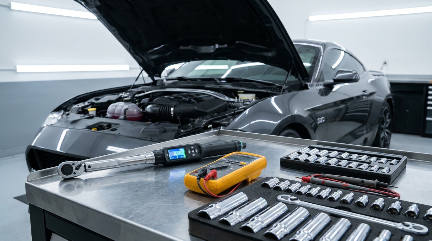
Maintaining the operational integrity of a motor vehicle requires strict adherence to a scheduled regimen of diagnostics and component servicing. The internal combustion engine, electrical grid, and suspension network function as a cohesive system that demands precise, systematic upkeep to prevent mechanical degradation. Neglecting baseline maintenance accelerates component wear, compromises passenger safety, and exponentially increases the probability of catastrophic failure. This document serves as a highly precise, process-oriented protocol designed to establish a standard operating procedure for automotive upkeep. Curated for the Automotive Hub within the Pick it Quick multi-category content platform, this guide provides unambiguous instructions for executing essential diagnostic checks, fluid verifications, and module replacements. By implementing this authoritative methodology, operators can effectively mitigate thermal stress, reduce mechanical friction, and ensure optimal vehicle performance across varying environmental conditions. The primary objective is to transition the operator from a reactive repair model to a proactive maintenance model. Executing the following standardized procedures will maximize component longevity and establish a reliable baseline for vehicle safety.
Baseline diagnostic protocol for tire pressure and tread integrity
The pneumatic tire assembly serves as the sole point of contact between the vehicle and the driving surface. Maintaining precise inflation pressure and adequate tread depth is critical for ensuring optimal load distribution, maximizing traction, and mitigating hydroplaning during adverse weather conditions. Tire pressure is dynamic; it fluctuates in direct proportion to ambient temperature changes, governed by the laws of thermodynamics. Consequently, pressure verification must be conducted on a strict monthly interval and prior to any extended operational periods.
To execute a highly accurate pressure diagnostic, the vehicle must remain stationary for a minimum of three hours to ensure the tires are at a stable, ambient temperature. Step 1: Locate the Original Equipment Manufacturer (OEM) placard affixed to the driver’s side door jamb to identify the exact target pressure, measured in Pounds per Square Inch (PSI). Step 2: Remove the protective valve stem cap from the wheel assembly. Step 3: Firmly press a calibrated digital or analog dial pressure gauge squarely onto the Schrader valve to obtain a reading. Step 4: Compare the recorded metric against the OEM specification. Utilize a compressed air system to incrementally introduce air, or depress the valve core to release excess pressure, until the exact target PSI is achieved. Reinstall the valve stem cap securely to prevent the ingress of particulate matter.
Simultaneously, the operator must assess the structural integrity of the tire tread. The tread matrix is engineered to evacuate water and maintain a mechanical grip on the asphalt. Step 1: Insert a dedicated tread depth gauge into the primary circumferential grooves of the tire. Step 2: Depress the measurement pin until it makes contact with the base of the groove. Step 3: Read the measurement in thirty-seconds of an inch. A reading of 2/32 of an inch constitutes the absolute legal minimum; however, component replacement is strictly mandated when the depth reaches 4/32 of an inch to maintain operational safety. Operators must also visually inspect the tread face for irregular wear patterns. Accelerated wear on the center axis indicates chronic overinflation, while accelerated wear on the lateral edges indicates chronic underinflation. Asymmetric wear across the tread block signifies a misalignment of the suspension geometry, requiring immediate mechanical rectification.
Systematic verification of engine lubrication and cooling systems
The internal combustion engine operates under extreme thermal and mechanical stress. The engine lubrication system is engineered to reduce friction between moving metallic components, while the liquid cooling system is designed to extract and dissipate excess thermal energy. A systematic verification of both fluid subsystems is paramount to preventing catastrophic engine failure.
Motor oil degrades over time, losing its viscosity and accumulating particulate matter. Step 1: Ensure the vehicle is parked on a perfectly level surface. Allow the engine to reach optimal operating temperature, then shut down the ignition and wait precisely five minutes to allow the oil to drain completely into the lower sump. Step 2: Locate and extract the engine oil dipstick. Step 3: Wipe the dipstick clean utilizing a lint-free shop towel to remove residual fluid. Step 4: Reinsert the dipstick fully into the guide tube until it seats completely. Step 5: Extract the dipstick a second time and hold it horizontally. The fluid level must register between the embossed minimum and maximum crosshatched indicators. If the level is deficient, add the OEM-specified viscosity grade oil in precise increments until the optimal volume is achieved. Inspect the fluid for a milky appearance, which indicates coolant contamination and requires immediate professional intervention.
The pressurized liquid cooling system requires equal vigilance. The coolant mixture, typically a formulated ratio of ethylene glycol and distilled water, elevates the boiling point and depresses the freezing point of the fluid. Caution: Never open the primary radiator cap while the engine is at operating temperature, as the system is highly pressurized and will cause severe thermal injury. Step 1: Locate the translucent plastic coolant recovery reservoir within the engine bay. Step 2: Visually inspect the fluid volume against the molded minimum and maximum fill lines on the exterior of the tank. Step 3: If the volume is below the minimum threshold, introduce the exact OEM-specified coolant formulation into the reservoir. Mixing incompatible coolant chemistries will precipitate a localized gelation process, severely restricting thermal transfer and causing internal engine damage.
Visual inspection of the electrical storage system and illumination components
The 12-volt electrical storage system, typically a lead-acid or absorbent glass mat (AGM) battery, provides the initial high-amperage current required to engage the starter motor and stabilizes the voltage grid during vehicle operation. Maintaining the physical integrity of this component ensures reliable ignition and prevents electronic module malfunction.
A precise visual inspection of the battery casing and terminals is required. Step 1: Examine the exterior housing for any signs of structural deformation, swelling, or electrolyte leakage. Step 2: Inspect the positive and negative terminal posts for the presence of a white or blue crystalline substance. This indicates oxidation and acidic corrosion, which severely impedes electrical conductivity. Step 3: To neutralize the corrosion, disconnect the negative terminal cable followed by the positive terminal cable. Step 4: Apply a localized solution of sodium bicarbonate and water to the oxidized areas. Agitate the surface with a dedicated wire brush until the crystalline structure is entirely dissolved. Step 5: Rinse the terminals with distilled water and dry thoroughly. Step 6: Reconnect the positive terminal followed by the negative terminal. Apply a precise coating of dielectric grease to the exposed metal surfaces to establish an impermeable barrier against future moisture ingress and oxidation.
Following the battery diagnostic, a comprehensive verification of all exterior illumination circuits must be executed to ensure compliance with visibility and signaling regulations. Step 1: Activate the primary headlamp circuit and verify the operation of both low-beam and high-beam filaments. Step 2: Engage the left and right directional indicators, ensuring the flash rate is consistent. A rapid flash rate indicates an open circuit or a failed filament in one of the bulbs. Step 3: Activate the hazard warning flashers to verify the corresponding circuit. Step 4: Utilize a reflective surface, or enlist the assistance of a secondary observer, to confirm the illumination of the rear tail lamps, primary brake lamps, center high-mounted stop lamp, and reversing lamps. Immediate replacement of any non-functional halogen or LED unit is mandatory for operational safety.
Procurement of baseline mechanical tools for basic vehicle servicing
Executing precise automotive maintenance protocols requires the utilization of correct mechanical apparatus. Attempting to service a vehicle with inadequate or improperly sized equipment will inevitably result in rounded fasteners, stripped threads, and compromised components. Establishing a baseline inventory of high-quality tools is a mandatory prerequisite for any DIY procedure. Operators can consult the Pick it Quick consumer guide platform to analyze technical specifications and procure optimal tool configurations.
The foundational component of any automotive toolkit is a comprehensive ratcheting socket set. Requirement 1: Procure a 3/8-inch drive ratcheting wrench constructed from forged vanadium steel. The set must include a complete sequence of six-point sockets in both metric (ranging from 8mm to 19mm) and standard SAE measurements. Six-point sockets provide superior torque application to the fastener flats, preventing corner deformation. Requirement 2: Include extension bars of varying lengths to access recessed bolts within the engine bay.
Accurate diagnostic equipment is equally critical. Requirement 3: Acquire a digital multimeter capable of measuring direct current (DC) voltage, resistance, and continuity. This device is indispensable for verifying battery resting voltage, which must optimally read 12.6 volts, and for diagnosing localized electrical faults. Requirement 4: Obtain a calibrated digital tire pressure gauge, which provides a more precise and repeatable metric than traditional analog pencil gauges.
Fluid management requires specialized implements to prevent environmental contamination and ensure accurate volumetric filling. Requirement 5: Procure dedicated, high-density polyethylene funnels for engine oil and coolant. These must be kept strictly separated to prevent cross-contamination of chemical fluids. Requirement 6: Acquire an appropriately sized oil filter wrench, either the cap-style or the adjustable band-style, to facilitate the removal of tightly torqued filter housings. Requirement 7: Always utilize appropriate personal protective equipment (PPE). Nitrile gloves are mandatory to prevent dermal absorption of hazardous hydrocarbons, and ANSI-rated polycarbonate safety spectacles are required to protect ocular structures from falling debris while operating beneath the vehicle.
Execution of engine and cabin air filtration module replacement
The filtration systems within a vehicle act as primary defense mechanisms against environmental contaminants. The engine air filter prevents the ingress of silica, particulate matter, and organic debris into the combustion chamber. A restricted engine air filter negatively impacts the stoichiometric air-fuel ratio, reducing volumetric efficiency and degrading engine performance. The cabin air filter serves a parallel function for the HVAC system, extracting airborne particulates and protecting the internal blower motor.
The protocol for replacing the engine air filter requires precision to ensure a hermetic seal. Step 1: Locate the primary cold air intake box within the engine compartment, typically a large plastic housing connected to the throttle body via a flexible tube. Step 2: Disengage the metallic tension clips or remove the retaining bolts securing the upper housing cover. Step 3: Lift the cover and extract the soiled pleated paper element. Step 4: Utilize a specialized shop vacuum or a clean damp cloth to extract any residual debris accumulated in the lower airbox housing. Step 5: Insert the replacement filtration element. It is critical to ensure the polyurethane perimeter gasket seats uniformly within the lower housing channel. Step 6: Re-secure the upper cover, verifying that no lateral gaps exist that could allow unfiltered air bypass.
The replacement protocol for the cabin air filtration module is typically executed from within the passenger compartment. Step 1: Locate the filter housing, which is universally positioned behind the passenger-side glove compartment. Step 2: Empty the glove compartment and release the lateral dampener rod on the exterior edge. Step 3: Compress the internal retaining tabs to drop the glove compartment entirely downward, exposing the HVAC blower assembly. Step 4: Unlatch the rectangular plastic access panel securing the filter compartment. Step 5: Extract the contaminated filter. Step 6: Insert the new cabin air filter. The operator must rigorously observe the directional airflow arrow printed on the filter frame, ensuring it points downward toward the blower motor. Secure the access panel and reassemble the glove compartment stops.
Protocol for seasonal thermal adaptation and environmental protection
Motor vehicles operate in dynamic environments that subject mechanical components to severe thermal fluctuations. Adapting the vehicle to these seasonal shifts is a mandatory procedure to prevent accelerated component degradation. A highly structured protocol must be implemented to transition the vehicle between extreme temperature ranges.
Winter operations demand specific modifications to combat sub-zero temperatures and compromised surface traction. Step 1: Transition the vehicle to specialized winter tires. These assemblies utilize a high-silica rubber compound engineered to remain pliable at temperatures below 45 degrees Fahrenheit, ensuring maximum adhesion to frozen asphalt. Step 2: Evacuate the standard windshield washer fluid reservoir and introduce a dedicated methanol-based solvent. Standard fluids will freeze within the reservoir and lines, resulting in a catastrophic rupture of the plastic components. Step 3: Utilize a specialized hydrometer to measure the specific gravity of the engine coolant. This diagnostic confirms the fluid maintains the precise chemical ratio required to prevent freezing and subsequent cracking of the engine block.
Conversely, summer operations subject the vehicle to intense thermal stress, requiring equal procedural vigilance. Step 1: Execute a rigorous inspection of the serpentine accessory drive belt. The elevated ambient heat accelerates the degradation of the ethylene propylene diene monomer (EPDM) rubber. The operator must inspect the ribbed side of the belt for micro-cracking, glazing, or material separation. Step 2: Verify the operational integrity of the primary electric radiator cooling fan. Allow the engine to idle until it reaches peak operating temperature; the fan must engage automatically to draw ambient air through the radiator fins. Step 3: Inspect the frontal area of the air conditioning condenser and the primary radiator. Utilize compressed air to carefully clear any accumulated biological debris or insects from the aluminum fins, ensuring unobstructed airflow and optimal thermal dissipation. Adhering strictly to these seasonal protocols isolates the vehicle from environmental extremes and guarantees continuous mechanical reliability.